Main
Adaptive gear variator. Presentation
Gear adaptive stepless transfer implements the science discovery of Professor K.S. Ivanov “Effect of Force Adaptation in Mechanics”: in the mechanism with two degrees of freedom the closed contour provides the adaptation of output shaft to the variable moment of resistance at the expense of change of its speed of rotation.
RESEARCH-AND-PRODUCTION ASSOCIATION
Research-and-production association “Gear continuously variable transmission — CVT” (RPA CVT) carries out the fundamental and applied researches in the field of search of new effects in mechanic and creates the essentially new gearings.
The RPA CVT have been developed the theory of adaptive gears which possess property to be independently adapted for variable load (without a control system), have been designed, created and tested the gear continuously variable transmissions of machines. Results of probes have been reported at numerous scientific forums, published in the press and have been supported by international innovative patents.
The RPA CVT machine-building manufacture base is determined by the contract on cooperation of next enterprises: Institute of Mechanics and Machine Sciences of Kazakhstan, Almaty University of Power Engineering and Telecommunications, East-Kazakhstan State University and Almaty Machine-Building Plant.
GEAR CONTINUOUSLY VARIABLE TRANCMISSION – CVT
Appointment
The Gear CVT is intended for motion transfer on working shaft of machine with variable technological resistance. Gear CVT provides rotation of output shaft with speed which depends on loading in the smooth diapason of transfer ratios. Mechanism of transmission contains toothed wheels with constant engagement. The mechanism works without a switching of transfers. The gear CVT (or adaptive-mechanical transmission) is created on discovery of Professor Ivanov K.S. «Effect of force adaptation in mechanics». According to this discovery a mechanism with a closed contour containing toothed wheels provides adjusting or adaptation to variable loading.
Comparison of transmissions
Continuously variable transmission (CVT) which is using now is hydro mechanical transmission. It contains hydraulic converter and multistage planetary mechanism with mechanism of switching of transfers. The hydraulic converter carries out an additional constraint between links of the planetary mechanism and provides transmission self-regulation. The transmission is complicated and bulky. Control system of transmission creates the change of transfers and does not provide continuous conformity of rotation speed of output shaft to loading on it.
Offered continuously variable transmission is adaptive mechanical transmission. It contains only an adaptive wheelwork and has the extremely simple design.
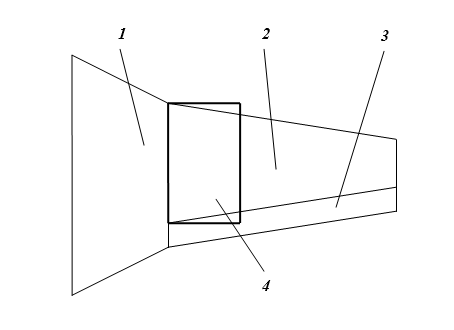
Fig. 1. Comparison of hydro mechanical and adaptive-mechanical transmissions
On fig. 1 the hydro mechanical transmission which has been using now is shown by thin lines.
It contains following parts:
1. Hydraulic converter.
2. Fixed-ratio transmission with 4th or 5th stages of toothed wheels.
3. Hydro mechanical switching mechanism.
The adaptive-mechanical transmission which does not have analogues in world practice is shown by thick lines. It contains only an adaptive wheelwork 4 — the self-regulated mechanism without any control system.
Theoretical substantiation
The discovery of effect of force adaptation in the mechanics is a theoretical basis of creation of essentially new self-controlled transmission with constant cogging of toothed wheels.
The adaptive mechanical continuously variable transmission represents the closed toothed differential mechanism with two degrees of freedom. The toothed differential mechanism having the closed contour with toothed wheels is capable to impose additional constraint on motion of links. Definability of motion of the gearing is theoretically proved at start-up regime (in a condition with one degree of freedom) and in operating regime of motion. The transmission provides also stop regime when a rotation of input shaft and stop of the output shaft takes place.
The find regularities are allow executing geometrical and dynamic synthesis of transmission on the set diapason of transfer ratios.
Description of adaptive-mechanical transmission
The adaptive mechanical transmission represents the closed differential mechanism with two degrees of freedom (fig. 2).
The basic parts:
0 – rack,
![]() – input carrier,
– input carrier,
![]() – output carrier,
– output carrier,
2 – input satellite,
5 – output satellite,
1, 4 – solar wheels united in block of wheels 1-4,
3, 6 – epicycle (ring) wheels united in block of wheels 3-6.
Geometrical parameters:
Radiuses ![]() of input carrier
of input carrier ![]() and output carrier
and output carrier ![]() .
.
Numbers of teeth of wheels ![]() .
.
Kinematic parameters:
Angular speed of input carrier ![]() is constant.
is constant.
Angular speed of output carrier ![]() depends on output loading.
depends on output loading.
Force parameters:
Input driving moment ![]() on input carrier
on input carrier![]() is constant.
is constant.
Output moment of resistance ![]() on output carrier
on output carrier![]() is variable and it is corresponding to external loading.
is variable and it is corresponding to external loading.
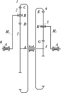
Fig. 2. Adaptive mechanical transmission (gear variator)
The input power ![]() is constant.
is constant.
The output power ![]() without account of efficiency is equal input power.
without account of efficiency is equal input power.
Work of transmission
The motion beginning:
The input driving moment is equal to output moment of resistance![]() . Transmission motion takes place in condition with one degree of freedom. Transmission is moving as a single whole.
. Transmission motion takes place in condition with one degree of freedom. Transmission is moving as a single whole.
Operating regime of motion:
Output moment of resistance starts to exceed the input driving moment![]() . The increase of output moment of resistance leads to decrease of angular speed of output carrier
. The increase of output moment of resistance leads to decrease of angular speed of output carrier ![]() at invariable input angular speed of input carrier. By this the balance of power remains
at invariable input angular speed of input carrier. By this the balance of power remains![]() . Relative motion of transmission links is beginning. Transmission motion in condition with two degrees of freedom takes place.
. Relative motion of transmission links is beginning. Transmission motion in condition with two degrees of freedom takes place.
Transfer ratio
![]() .
.
Maximum transfer ratio
![]() .
.
Diapason of change of transfer ratio
![]() .
.
Transmission admits a stop regime of motion at rotation of input shaft and stop of output shaft by way of transition into condition with one degree of freedom. In stop regime of motion ![]() .
.
Connection between force parameters and kinematic parameters of transmission is defined by the following theorem:
Mobile closed four links contour in the kinematic chain imposes a constraint on motion of links of this chain. This constraint leads to equilibrium on principle of virtual works
![]() . (1)
. (1)
From here
![]() . (2)
. (2)
It means that output angular speed inversely to variable output moment of resistance![]() at the constant input power
at the constant input power ![]() .
.
Equation (2) defines effect of force adaptation of the mechanism. This effect is leading to change of speed of rotation of the output shaft depending on loading on it.
Efficiency of the adaptive gear variator
The adaptive gear variator has two degree of freedom. However the efficiency of this variator brand differs from efficiency of variators used in technics with two degree of freedom (a clutch friction coupling, hydrodynamic transfer) in which the friction carries out impellent function. In a gear adaptive variator impellent function is not based on friction use. Impellent function is carried out by the closed contour containing toothed wheels. An energy loss on a friction in a gear adaptive variator is connected only with motion of toothed wheels as in a usual gear variator and not based on friction use as impellent function. Therefore efficiency of an adaptive gear variator considerably above efficiency of a friction coupling or efficiency of hydrodynamic transfer.
Hydrodynamic transfer is transfer with two degree of freedom. The transfer relation of hydrodynamic transfer can change from 1 to the maximum value (nearby 2) when there is an output shaft stop. At the moment of a stop of the output shaft of efficiency it is equal 0. Mechanical adaptive transfer works in a similar range of transfer relations. Therefore mechanical adaptive transfer will have the analogous efficiency.
However, in hydrodynamic transfer the output moment is created by an internal hydraulic moment of resistance which depends on a difference of angular speeds of pump and turbine wheels. The kinematic joint of pump and turbine wheels cannot be an ideal kinematic couple. This joint functionally exists for transformation of an internal moment of resistance to an external output moment of resistance. The hydraulic moment of resistance simultaneously defines factor of an energy loss. Therefore efficiency of hydrodynamic transfer linearly decreases depending on loading.
Basic other dependence occurs in mechanical adaptive transfer. This dependence is defined by the formula (2) connecting the external moments and speeds. The internal mechanical moment in the closed contour of mechanical adaptive transfer also occurs. However this moment in transfer with ideal communications does not create an energy loss, as power (or work) internal forces is equal to null. In mechanical adaptive transfer there is only a disproportionation of speeds of motion of links in the closed contour.
Thus, efficiency of mechanical adaptive transfer functionally does not depend on external loading and matches to efficiency of the planet gear. At the moment of qualitative change of structure of a variator at a stop of a output link of efficiency instantly gets a zero value.
Efficiency adaptive an adaptive gear variator (fig. 2) or efficiency of the adaptive gearing we will define by formula
 , (3)
, (3)
Where ![]() — a useful power on output carrier
— a useful power on output carrier ![]() ,
,
![]() — The spent power on input carrier
— The spent power on input carrier ![]() .
.
The adaptive gearing (fig. 2) represents a gear planetary variator which depending on the enclosed loading can move with one or with two degree of freedom. Efficiency of adaptive transfer depends on a motion regime.
The adaptive gearing moves with one degree of freedom if the output moment of resistance is equal to the input driving moment
![]() .
.
In this case the closed contour which is switching on toothed wheels 1, 2, 3, 6, 5, 4, moves as a single whole without relative mobility of toothed wheels in a contour. A friction loss occurs only in two rotational kinematic couples ![]() , connecting the input and output carriers with a rack. Therefore
, connecting the input and output carriers with a rack. Therefore
![]() ,
,
Where ![]() — efficiency of rotational pair
— efficiency of rotational pair ![]() .
.
Efficiency of all variator in a regime of motion with one degree of freedom we will gain from the formula (3) after substitution of value ![]()
![]() .
.
The adaptive gearing moves with two degree of freedom, if output moment of resistance more than the input driving moment
![]() .
.
In this case there is an internal relative motion of wheels 1, 2, 3, 6, 5, 4 in the closed contour. A friction loss occurs not only in two rotational kinematic couples ![]() , connecting the input and output carriers with a rack, but also in a contour containing 4 rotational kinematic couples (type
, connecting the input and output carriers with a rack, but also in a contour containing 4 rotational kinematic couples (type ![]() ) and 4 higher kinematic couples (type
) and 4 higher kinematic couples (type ![]() — gearing of teeth of wheels). Therefore
— gearing of teeth of wheels). Therefore
![]() ,
,
Where ![]() — efficiency of the higher kinematic couple of type
— efficiency of the higher kinematic couple of type ![]() .
.
Efficiency of all variator in a regime of motion with two degree of freedom we will gain from the formula (3) after substitution of value ![]()
![]() .
.
Practical implementation
Practical implementation is including the next:
1. Patent of Germany № 20 2012 101 273.1.
Patent of Russia № 2398989.
Patents of Kazakhstan: №3208, №11042, №12236, №14477, №17378, № 023907, №24181, №24625, № 26107, № 79226.
2. On fig. 3 the assembly drawing of adaptive mechanical transmission of the conveyor drive is presented.
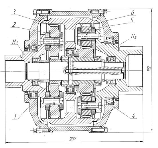
Fig. 3. Assembly drawing of adaptive mechanical transmission of the conveyor drive
3. Computer animation of adaptive mechanical transmission is presented on the site http://www.madbass.narod.ru and on fig. 4. It shows motion of links at change of external loading. The animation model contains electric motor (of grey color at the left), transmission without the case (input carrier with input satellite of green color, block of solar wheels of red color, block of ring wheels of dark blue color and output satellite of green color with output carrier) and brake (of red color at the right) which is simulating an output moment of resistance. The electric motor has constant parameters of power (angular speed and driving moment). The brake creates a variable moment of resistance. When the output moment of resistance is increasing then the output carrier rotation is decreasing and on the contrary.
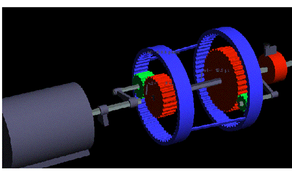
Fig. 4. Animation model of adaptive mechanical transmission
4. Acting pattern of adaptive mechanical transmission (fig. 5). The pattern is confirming the presence of force adaptation in a wheelwork with the closed contour.
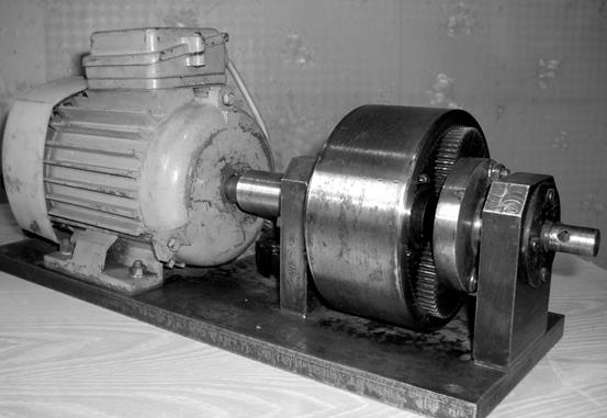
Fig. 5. Acting pattern of adaptive mechanical transmission
5. Computer model of adaptive mechanical transmission (fig. 6).
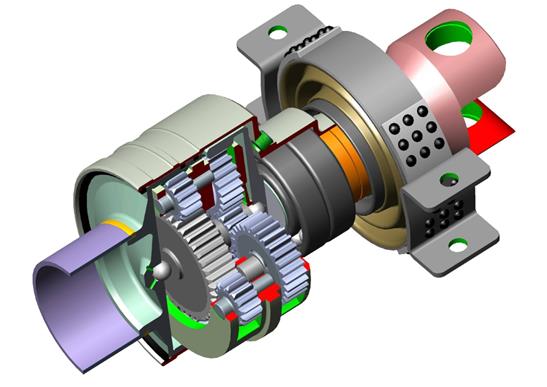
Fig. 6. Computer model of adaptive mechanical transmission
6. Tests adaptive-mechanical stepless adjustable transfer.
Stock-taking of effect of power adaptation in stepless adjustable transfer has been executed on the test-bed (fig. 7).
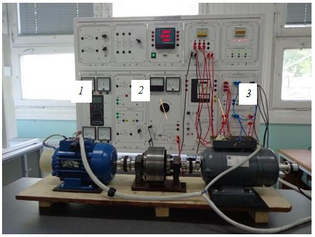
Fig. 7. Stand for test adaptive-mechanical stepless adjustable transfer
At the test-bed the electric motor 1 with constant power which drives an adaptive variator 2 (adaptive-mechanical transfer) is presented. The variator transfers motion to the electric oscillator 3 which simulates an external variable load. External loading changes by change of a strength of current in a field winding of the oscillator 3. Meters display a moment of resistance on output shaft of a variator 2 and frequency of its twirl at a constant input power of the electric motor 1.
On fig. 8 the experimental tractive characteristic of a gear adaptive variator in the form of the schedule of change of the traction moment on output shaft in Nm is presented depending on speed of its twirl in rpm.
The traction moment on output shaft of the mechanism in operating regime of motion is equal to a variable moment of resistance.
The tractive characteristic contains following sections. A regime of start-up — curve ![]() and the operating regime of motion — curve
and the operating regime of motion — curve ![]() .
.
In a start-up regime at electric motor turning on the driving moment sweepingly changes from null to the rating value matching to power of the electric motor. The mechanism moves in a start-up regime (curve ![]() ) in a condition with one degree of freedom as a single whole. The internal relative motion of wheels in the closed contour is absent. The mechanism output shaft is twirled with rated speed of twirl of the shaft of the electric motor. In point
) in a condition with one degree of freedom as a single whole. The internal relative motion of wheels in the closed contour is absent. The mechanism output shaft is twirled with rated speed of twirl of the shaft of the electric motor. In point ![]() the traction moment on the output shaft of the adaptive mechanism is equal of the characteristic to the input moment or the moment on electric motor shaft
the traction moment on the output shaft of the adaptive mechanism is equal of the characteristic to the input moment or the moment on electric motor shaft ![]() . Speed twirls (rotational speed) of the output shaft is equal to input shaft rotational speed
. Speed twirls (rotational speed) of the output shaft is equal to input shaft rotational speed![]() .
.
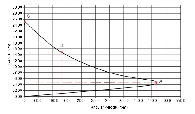
![]() — motion in a condition with one degree of freedom in the absence of internal mobility in a contour,
— motion in a condition with one degree of freedom in the absence of internal mobility in a contour, ![]() — motion with two degree of freedom (operating regime),
— motion with two degree of freedom (operating regime), ![]() — an intermediate point,
— an intermediate point, ![]() — the operating conditions end (the maximum moment of resistance and a stop).
— the operating conditions end (the maximum moment of resistance and a stop).
Fig. 8. An experimental tractive characteristic of the gear adaptive mechanism
The operating regime of motion begins in point ![]() of curve
of curve ![]() when the output moment of resistance starts to exceed nominal traction moment
when the output moment of resistance starts to exceed nominal traction moment ![]() . In this case the mechanism passes in a condition with two degree of freedom. There is a power adaptation. The output shaft rotational speed independently changes in inverse relationship from a moment of resistance. The input moment and an input rotational speed remain without change. They are equal to matching nominal values of parameters of the electric motor.
. In this case the mechanism passes in a condition with two degree of freedom. There is a power adaptation. The output shaft rotational speed independently changes in inverse relationship from a moment of resistance. The input moment and an input rotational speed remain without change. They are equal to matching nominal values of parameters of the electric motor.
For example, in point ![]() the traction moment on the output shaft and matching to it moment of resistance has value
the traction moment on the output shaft and matching to it moment of resistance has value ![]() , the output shaft rotational speed is equal
, the output shaft rotational speed is equal ![]() .
.
The maximum traction moment on the output shaft occurs in point ![]() . The maximum traction moment is equal In this point to maximum moment of resistance
. The maximum traction moment is equal In this point to maximum moment of resistance ![]() . The output shaft rotational speed at the approach to point
. The output shaft rotational speed at the approach to point ![]() turns in minimum
turns in minimum ![]() , and then in point
, and then in point ![]() occurs a stop of the output shaft of mechanism
occurs a stop of the output shaft of mechanism ![]() . The input shaft continues to be twirled with rated speed of twirl of electric motor
. The input shaft continues to be twirled with rated speed of twirl of electric motor ![]() . The mechanism passes in a condition with one degree of freedom when the input shaft is twirled and the output shaft is stopped. The so-called stop — regime occurs.
. The mechanism passes in a condition with one degree of freedom when the input shaft is twirled and the output shaft is stopped. The so-called stop — regime occurs.
Theoretical results are co-ordinated with results of tests at the stand. The closed contour as a part of the kinematic chain with two degree of freedom in the presence of ideal constraints provides definiteness of motion as in a condition with two degree of freedom (in operating regime of motion) and in a condition with one degree of freedom (at start-up).
Conclusion
Creation of gear adaptive mechanical transmission in the form of closed gear differential mechanism with two degrees of freedom is theoretically proved.
Gear adaptive mechanical transmission with constant cogging of wheels is the simple adjustable transmission and it has the reliability matching to reliability of wheelwork. The specified properties allow using transmission for the drive of machines with variable technological resistance. The transmission can be used as in easy drives of machines (velocipedes, motorcycles, manipulators), and in heavy drives of machines (cars, lorries, autobuses, tractors, bulldozers, drilling rigs, rolling mills) including in motor-wheels.